TERMS AND DEFINITIONS
GB/T10107.1 the basic planetary transmission terms of cycloidal-pin wheel and JB/T10419 cycloidal-pin wheel planetary transmission, cycloid gear, pin wheel, and accuracy terms all suitable for this standard.
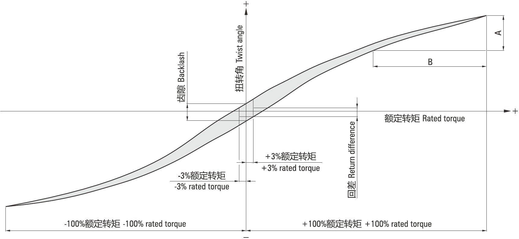
■Hysteresis Curve
The fixed input gear is applied to the output to obtain the corresponding relationship between the torque and the torsion angle, and the hysteresis curve is drawn. (Figure 1)
■Transmission Accuracy
Transmission accuracy (θ): refers to the input with arbitrary rotation angle when the theory of rotation angle (θin) and the actual output rotation angle (θout) between poor and formula: θ=θin/k-θout (k—Ratio values).
■Backlash
The intermediate point of the hysteresis curve of the nominal torque of 3%. (Figure 1)
■Backlash
Torsion angle at the rated torque of zero. (Figure 1)
■Torsional Stiffness
Torsional stiffness = B/A. (Figure 1)
•Figure 1 — Hysteresis curve Unit: (Nm/arc min)
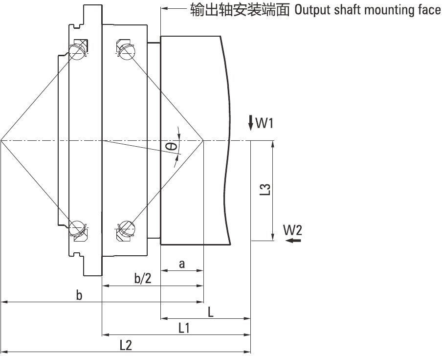
■New Main Bearing Rigid Definition:
Moment rigidity
When subjected to an external load moment, the output shaft is tilted in proportion to the load moment, resulting in an angle 0 (N'm/arc.min).
θ=(W1︱1-W2︱3)/(Mt X 103) Mt is the bending stiffness (As shown).
Bending stiffness represents the stiffness of the main bearing, expressed in terms of the load torque required for a unit angle of inclination (1 arc.min).
|
Model
|
Moment Of Rigidity (Nm/Arc.min)
|
a
(mm)
|
b
(mm)
|
Model
|
Moment Of Rigidity (Nm/Arc.min)
|
a
(mm)
|
b
(mm)
|
|
150BX
|
372
|
20.1
|
113.3
|
10CBX
|
421
|
28.0
|
119.2
|
|
190BX
|
931
|
29.6
|
143.7
|
27CBX
|
1068
|
38.2
|
150.3
|
|
220BX
|
1176
|
33.4
|
166.0
|
50CBX
|
1960
|
50.4
|
187.1
|
|
250BX
|
1470
|
32.2
|
176.6
|
100CBX
|
2813
|
58.7
|
207.6
|
|
280BX
|
2940
|
47.8
|
210.9
|
200CBX
|
9800
|
76.0
|
280.4
|
|
320BX
|
4900
|
56.4
|
251.4
|
320CBX
|
12740
|
114.5
|
360.5
|
■Explanation Of Terms Concept:
|
Noun
|
Explanation
|
Effect
|
Remarks
|
|
Speed ratio
|
This refers to the output and input ratio.
|
|
RV-C difference
|
|
Rated speed
|
Speed at rated life test.
|
Life calculation
|
|
|
Rated torque
|
Torque at rated life test.
|
Life calculation
|
|
|
Rated life
|
Torque at rated life test.
|
Life calculation
|
|
|
Allowable maximum output torque
|
Refers to the maximum allowable speed.
|
Speed check
|
The main use, the shell temperature can not exceed 60°C.
|
|
Permissible torque at start and stop
|
When starting (stop), there is inertia torque, which is much higher than the gearbox stable time torque.
|
Start, stop when the torque check.
|
|
|
Instantaneous maximum allowable torque
|
Due to an emergency stop or an external shock, the gear unit may be subjected to a large torque.
|
Impact life calculation
|
|
|
Moment of rigidity
|
When the reducer output shaft deflection 1arc min, the reducer to withstand the bending moment.
|
|
|
|
Torsion rigidity
|
When the reducer output shaft rotation 1arc min, the reducer to withstand the torque.
|
|
|
|
Allowable moment
|
Refers to the reducer can bear external bending moment.
|
|
|
|
Instantaneous allowable moment
|
Due to emergency stop, etc., caused by special circumstances instantaneous maximum moment.
|
Bending moment check
|
|
|
Allow thrust
|
Reducer can withstand the maximum load force.
|
Thrust check
|
|
|
Empty trip
|
Hysteresis curve at the rated torque ±3% of the width of the focus of the torsion angle.
|
Accuracy
|
|
|
Backlash
|
Hysteresis Curve Torque at "zero".
|
Accuracy
|
|
|
Angle of transmission error
|
Angle of transmission error refers to the input of any angle, the theoretical output choice angle and the actual output angle between the error.
|
Accuracy
|
|
|
No load running torque
|
No load operation reducer input torque required.
|
|
|
|
Increase speed start torque
|
The minimum output torque that reverses the gear unit is applied.
|
|
|
PRODUCT STRUCTURE, MODEL AND DIMENSION
The reducer is composed by output flange,s upporting flange, needle gear housing, cycloid gear, crank shaft, planetary gear, gear pin, input gear (optional), main bearing, cone roller bearings, needle roller bearings to keep frame and oil seal.
■Reducer Structure
•Figure 2-E series reducer structure
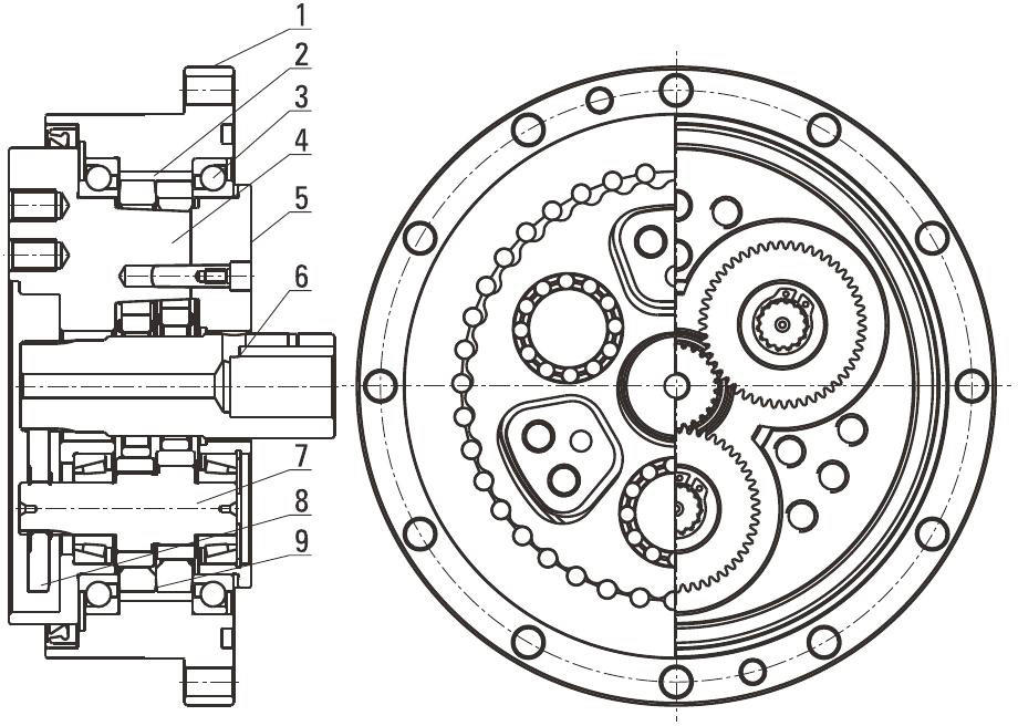
1 -Needle tooth shell
2-Pin gear
3-Main bearing
4-Output flange
5-Supporting flange
6-Input shaft
7-Crankshaft
8-Planetary gear
9-Cycloidal gear
•Figure 3-C series reducer structure

1 -Cycloidal gear
2-Output flange
3-Needle tooth shell
4-Pin gear
5-Main bearing
6-Supporting flange
7-Crankshaft
8-Planetary gear
9-Central gear
10-Low speed tube
■Reducer Outline Dimension
•E series reducer outline dimensions see P11 ~P21.
•C series reducer outline dimensions see P22-P30.
■Using Environment
• In the following environmental conditions, the reducer should be able to operate normally:
The highest ambient temperature is changed by seasons and less than 40°C.
The lowest ambient temperature is -10°C.
■Model Number
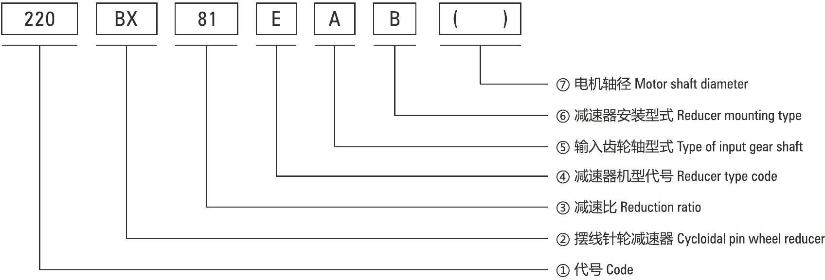
•①Code, specific see table 1
Reducer Code
|
E Series
|
C Series
|
|
Code
|
Outline dimension (mm)
|
General model
|
Code
|
Outline dimension (mm)
|
The original code
|
|
120
|
0122
|
6E
|
10C
|
0145
|
150
|
|
150
|
CP145
|
20E
|
27C
|
0181
|
180
|
|
190
|
0190
|
40E
|
50C
|
0222
|
220
|
|
220
|
0222
|
80E
|
100C
|
0250
|
250
|
|
250
|
CP244
|
110E
|
200C
|
0345
|
350
|
|
280
|
0280
|
160E
|
320C
|
0440
|
440
|
|
320
|
0325
|
320E
|
500C
|
0520
|
520
|
|
370
|
0370
|
450E
|
/
|
/
|
/
|
•②BX: Cycloidal pin wheel reducer
•③81: Gear ratio, specific see table 2
Reduction Ratio
|
E Series
|
C Series
|
|
Code
|
Reduction ratio (output flange output)
|
New code
|
Monomer reduction ratio
|
|
120
|
43, 53.5, 59, 79, 103
|
10CBX
|
27.00
|
|
150
|
81, 105, 121, 141, 161
|
27CBX
|
36.57
|
|
190
|
81, 105, 121, 153
|
50CBX
|
32.54
|
|
220
|
81, 101, 121, 153
|
100CBX
|
36.75
|
|
250
|
81, 111, 161, 175.28
|
200CBX
|
34.86
|
|
280
|
81, 101, 129, 145, 171
|
320CBX
|
35.61
|
|
320
|
81, 101, 118.5, 129, 141, 171, 185
|
500CBX
|
37.34
|
|
370
|
81, 101, 118.5, 129, 154.8, 171, 192.4
|
/
|
/
|
|
Note 1: E series, such as by the shell (pin shell) output, the corresponding reduction ratio by 1.
|
|
Note 2: C series gear ratio refers to the motor installed in the casing of the reduction ratio, if installed on the output flange side, the corresponding reduction ratio by 1.
|
•④Reducer type code
RVE:Main bearing built-in E type
RVC:Hollow type
REA:Elk With input flange E type
RCA:With input flange hollow type
•⑤Enter the gear shaft type and motor shaft diameter
A:Standard Type A, E Series Input Gear A-axis (P19).
C Series represents the standard sun gear. Standard Type B, E Series Input Gear 6-axis (P19).
Z:Special matching type.
W:Nothing.
TB:C series synchronous pulley input type.
•⑥Reducer mounting type
B:Output shaft bolt fastening connection
P:Output shaft bolts and locating pins with the type
• ⑦Motor shaft diameter
TECHNICAL REQUIREMENT
■Appearance Quality, Marks: Reducer Appearance Should Be Neat, Beautiful, Clear, Correct
•Reducer's appearance should not be bumps, scratches, burrs, pits and coeeosion etc.
•Fastener connection should be firm, lock, seal should be reliable.
•Mark should be clear and correct after the testing, the mark should be clearly.
•Reducer should have reliable anti rust measures.
■Basic Dimensions
•Deceleration device installation size, size should be consistent with the P11 ~P21 and P22~P30 of the drawing or customer requirements and customer confirmation drawings.
•Input shaft and installation flange can be produced as customer's requirements, before the producting, it should get customer's comfirmation drawing.
■Noise
•The reducer running in no-load input speed is less than or equal to 3000r/min, the noise should be less than 70+3dB(A).
■Idie Test
•Noload operating test: After reducers work under noload for 10min with input speed ≤3000r/min, reducer can run steadily, no abnormal or impacting noise.
•Ratio test: The speed ratio of the reducer should be in accordance with the calibration value.
■Torque
•Reducers work continuously for over 2 hours at rated torque, no abnormal noise.
•After reducers work continuously, reducer's temperature should less than 45℃, bearing temperature is < 95℃.
•Gear reducer transmission efficiency should meet the requirements of table 3, table 4.
• E series reducer output torque in accordance with the provisions of table 3.
• C series reducer output torque in accordance with the provisions of table 4.
•Table 3-E series output torque and efficiency
|
Model\Qutput Speed
|
5 r/min
|
18 r/min
|
25 r/min
|
30 r/min
|
Maximum Allowable Loss Out Speed r/min
|
|
Output Torque
N.m
|
Input Power
Kw
|
Output Torque
N.m
|
Input Power
Kw
|
Efficiency
%
|
Output Torque
N.m
|
Input Power
Kw
|
Output Torque
N.m
|
Input Power
Kw
|
|
120BX
|
115
|
0.075
|
64
|
0.15
|
80
|
62
|
0.2
|
64
|
0.25
|
100
|
|
150BX
|
245
|
0.160
|
170
|
0.40
|
80
|
153
|
0.5
|
153
|
0.60
|
75
|
|
190BX
|
612
|
0.400
|
425
|
1.00
|
80
|
367
|
1.2
|
382
|
1.50
|
70
|
|
220BX
|
1146
|
0.750
|
743
|
1.75
|
80
|
673
|
2.2
|
637
|
2.50
|
70
|
|
250BX
|
1528
|
1.000
|
934
|
2.20
|
80
|
978
|
3.2
|
892
|
3.50
|
50
|
|
280BX
|
2292
|
1.500
|
1571
|
3.70
|
80
|
1437
|
4.7
|
1274
|
5.00
|
45
|
|
320BX
|
4584
|
3.000
|
2972
|
7.00
|
80
|
2903
|
9.5
|
2802
|
11.0
|
35
|
|
370BX
|
6112
|
4.000
|
3905
|
9.20
|
80
|
/
|
/
|
/
|
/
|
25
|
|
Note 1: The rated torque is the output torque of the output speed of 18 r/min. The input power considers the efficiency of the reducer.
|
|
Note 2: Torque calculation formula:
T=9549XPXη/N (T: Torque Nm, P: Power Kw, N: Speed r/min, η: Efficiency %).
|
•Table 4-C output series torque and efficiency
|
Model/
Output Speed
|
5 r/min
|
18 r/min
|
25 r/min
|
30 r/min
|
Maximum Allowable
Loss Out Speed
|
|
Output Torque
|
Input Power
|
Output Torque
|
Input Power
|
Efficiency
|
Output Torque
|
Input Power
|
Output Torque
|
Input Power
|
|
Model
|
N.m
|
Kw
|
N.m
|
Kw
|
%
|
N.m
|
Kw
|
N.m
|
Kw
|
r/min
|
|
10CBX
|
134
|
0.09
|
99
|
0.24
|
78
|
89
|
0.3
|
87
|
0.35
|
80
|
|
27CBX
|
372
|
0.25
|
269
|
0.65
|
78
|
239
|
0.8
|
223
|
0.90
|
60
|
|
50CBX
|
745
|
0.50
|
455
|
1.10
|
78
|
447
|
1.5
|
434
|
1.75
|
50
|
|
100CBX
|
1490
|
1.00
|
994
|
2.40
|
78
|
894
|
3.0
|
819
|
3.30
|
40
|
|
200CBX
|
2235
|
2.00
|
1986
|
4.80
|
78
|
1788
|
6.0
|
1638
|
6.60
|
30
|
|
320CBX
|
4470
|
3.00
|
3103
|
7.50
|
78
|
2830
|
9.5
|
/
|
/
|
25
|
|
500CBX
|
7003
|
4.70
|
4966
|
12.0
|
78
|
/
|
/
|
/
|
/
|
20
|
|
Note 1: The rated torque is the output torque of the output speed of 18rpm. The input power considers the efficiency of the reducer.
|
|
Note 2: Torque calculation formula:
T=9549XPXn/N (T: Torque Nm, P: Power Kw, INI: Speed RPM, η: Efficiency %).
|
■Transmission Precision, Torsional Stiffness, Backlash And Backlash
•The torsional stiffness, backlash and backlash of the gear reducer shall meet the requirements of table 5 and table 6.
•The transmission accuracy of gear reducer shall conform to the requirements of table 5 and table 6.
■Life
•When the reducer is working on rated speed and on-loading, reducer's lift time is more than 6000 hours.
■Allowable Torque
•The allowable torque of the gear reducer shall meet to the requirements of table 5 and table 6.
■Overload
•After reducer working under over-load for 5min with 125% rated torque, dudring the running, it have no noise and other damage
■Reducer Technical Parameters See Table 5And Table 6
•Table 5-C series of technical parameters
|
Model\Project
|
Retarder Monomer Reduction Ratio
|
Allowable Moment
N.m
|
Torsional Rigidity
N.m/(Arc.min)
|
Instantaneous Maximum Torque
N.m
|
Transmission Accuracy
Arc.min
|
Backlash Of Backlash
Arc.min
|
Life
h
|
Retarder Inertia Moment Kg.m2
|
Weight
kg
|
|
10CBX
|
27.00
|
686
|
47
|
490
|
1.0
|
1.0
|
6000
|
1.380X10⁵
|
4.60
|
|
27CBX
|
36.57
|
980
|
147
|
1323
|
1.0
|
1.0
|
6000
|
0.550X10⁴
|
8.50
|
|
50CBX
|
32.54
|
1764
|
255
|
2450
|
1.0
|
1.0
|
6000
|
1.820X10⁴
|
14.6
|
|
100CBX
|
36.75
|
2450
|
510
|
4900
|
1.0
|
1.0
|
6000
|
0.475X10³
|
19.5
|
|
200CBX
|
34.86
|
8820
|
980
|
9800
|
1.0
|
1.0
|
6000
|
1.390X10³
|
55.6
|
|
320CBX
|
35.61
|
20580
|
1960
|
15680
|
1.0
|
1.0
|
6000
|
0.518X10'2
|
79.5
|
|
500CBX
|
37.34
|
34300
|
3430
|
24500
|
1.0
|
1.0
|
6000
|
0.996X10²
|
154
|
•Table 6-E series of technical parameters
|
Model\Project
|
Ratio Value
|
Allowable Moment
|
Torsional Rigidity
|
Instantaneous Maximum Torque
|
Transmission Accuracy
|
Backlash Of Backlash
|
Life
|
Weight
|
|
Axis Output
|
Shell Output
|
N.m
|
N.m/(Arc.min)
|
N.m
|
Arc.min
|
Arc.min
|
h
|
kg
|
|
120BX
|
53.50
|
52.50
|
196
|
20
|
294
|
1.5
|
1.5
|
6000
|
2.50
|
|
59.00
|
58.00
|
|
79.00
|
78.00
|
|
103.0
|
102.0
|
|
150BX
|
81.00
|
80.00
|
880
|
49
|
820
|
1.0
|
1.0
|
6000
|
4.70
|
|
105.0
|
104.0
|
|
121.0
|
120.0
|
|
141.0
|
140.0
|
|
161.0
|
160.0
|
|
190BX
|
81.00
|
80.00
|
1600
|
108
|
2000
|
1.0
|
1.0
|
6000
|
9.30
|
|
105.0
|
104.0
|
|
121.0
|
120.0
|
|
153.0
|
152.0
|
|
220BX
|
81.00
|
80.00
|
2000
|
196
|
3600
|
1.0
|
1.0
|
6000
|
13.1
|
|
101.0
|
100.0
|
|
121.0
|
120.0
|
|
153.0
|
152.0
|
|
250BX
|
81.00
|
80.00
|
2900
|
294
|
5380
|
1.0
|
1.0
|
6000
|
17.4
|
|
111.0
|
110.0
|
|
161.0
|
160.0
|
|
175.28
|
174.28
|
|
280BX
|
81.00
|
80.00
|
3900
|
392
|
7800
|
1.0
|
1.0
|
6000
|
26.4
|
|
101.0
|
100.0
|
|
129.0
|
128.0
|
|
145.0
|
144.0
|
|
171.0
|
170.0
|
|
320BX
|
81.00
|
80.00
|
7000
|
980
|
15600
|
1.0
|
1.0
|
6000
|
44.3
|
|
101.0
|
100.0
|
|
118.5
|
117.5
|
|
129.0
|
128.0
|
|
141.0
|
140.0
|
|
171.0
|
170.0
|
|
185.0
|
184.0
|
|
370BX
|
81.00
|
80.00
|
8820
|
1176
|
22000
|
1.0
|
1.0
|
6000
|
66.4
|
| 101.0 |
100.0 |
| 118.5 |
117.5 |
|
129.0
|
128.0
|
| 154.8 |
153.8 |
| 171.0 |
170.0 |
| 192.4 |
191.4 |
LUBRICATION
■Reducer using lubricating oil: Molywhite RE-00 or VIGO- grease REO other similar grade precision reducer special grease
■The lubrication grease is not filled before gearbox leave factory. Please fill in the suggested lubrication grease during assembly, the amount is roughly 90% of the gearbox inside cavity volume
■Lubricating grease standard replacement time is 20000 hours. When the grease is contaminated or is used in harsh environment, it is necessary to check the condition of aging and pollution, and to change the time
 EN
EN


.jpg?imageView2/2/w/370/h/370/format/jpg/q/75)