S1 Series Low Voltage Servo Driver Suppliers

Home / Products / Motor Driver & Controller / AC Speed Controller / S1 Series Low Voltage Servo Driver

Features

   
Quick Response
Speed loop bandwidth 1.2KHZ
Optimized feedforward control algorithm
Improved dynamic response
Shortened setting time
Precise Control Accuracy
Support 17/23-bit absolute encoder
More precise command following and more accurate stopping
The setting time could reach to 1ms
Strong Vibration Suppression
Easy to Operate & Configure
Guided configuring
Human-oriented operation
DriverStudio config motor parmeter
Monitoring data & wave profile
Standard Communication Protocol
Support ModBus, CANopen communication protocol
Compatible with various PLCs
Usage of Cascaded drivers
● Various Control Modes
Profile Position→Profile Velocity→Profile Torque→Pulse Position→Homing→Analog Speed→Analog Torque


Attention:
Pay attention to the following precautions about installation, wiring, operation, maintenance and inspection in order to avoid damage to people and property caused by misuse. 

1】Please connect the ground wire to the terminal with earthing mark to ensure the servo system is firmly grounded;
2】Please do not replace the motor, wire or touch the wiring terminals within 5 minutes after turning off the power, otherwise there is a risk of electric shock;
3】Please do not touch the heat sink, motor, and braking resistor during operation to avoid burns;
4】Please do set over-current protection device, residual current circuit breaker and emergency stop device, and confirm their effectiveness before operation;
5】Please set an external emergency stop circuit to ensure that the operation can be stopped in time and the power supply can be cut off in an emergency;
6】Please run the servo motor with no load first to avoid accidents before trial run;
7】Please do not turn on/off the servo driver power frequently;
8】It is strictly forbidden to perform installation, wiring and other operations under power-on conditions;
9】Please do not connect the motor wire terminal to the main supply;
10】Please do not disassemble, modify or repair the servo motor driver by yourself;
11】Please turn off the driver’s power supply when if it occurs error;
12】The power must be off if it is not used for a long time.

Storage Environment:
This product must be placed in the packaging box before installation. If it is not used temporarily, please pay attention to the following items when storing
in order to make the product comply with our company's protection scope and future maintenance:

● The environment temperature of the storage location must be within the range of -20°C to +80°C;
● The relative humidity of the storage location must be within the range of 0% to 90% without condensation;
● Avoid storage in an environment containing corrosive gas or liquid.

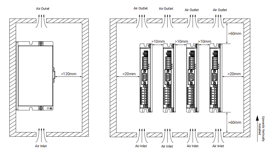
Installation Environment:
● The working environment temperature of the servo unit: 0~45℃;
● Humidity: below 90%RH (relative humidity);
● Vibration: 4.9m/s², applicable altitude: lower than 1000m, lower power is necessary if higher than 1000m;
● To avoid freezing or condensation
● Please use it under environmental temperature below 45°C to ensure the reliability of long-term use.


 S1 Series Servo Driver Model Description:


S1 Series Servo Motor Driver Specifications:
Model
ZDRV.S10-200L-RCB
ZDRV.S10-400L-RCB
ZDRV.S10-750L-RCB
ZDRV.S10-1K5L-RCB
Rated Input Voltage
20VDC~70VDC
Output
Rated Current
8Arms
15Arms
Could reach to 12Arms without auxiliary cooling
25Arms
Could reach to 20Arms without auxiliary cooling
40Arms
Could reach to 30Arms without auxiliary cooling
Peak Current
34Ap
63Ap
88Ap
141Ap
Encoder
Incremental (single-ended signal or differential single, 5V) / absolute value (RS485, 5V)
Dynamic Brake
External braking resistor, setting via software
Overvoltage Alarm Voltage
DC65V±1V
Undervoltage Alarm Voltage
DC18V±1V
Overload Time
2.5~3 times overload, max. duration 5s
Cooling Method
▲Natural cooling
Note: For S10-400L, S10-750L, S10-1K5L , the output current of 15Arms, 25Arms, 40Arms are test results that the driver is installed on a auxiliary cooler (AL6063 black oxide 300*300*10mm).

S1 Series Servo Motor Driver Dimensions & Installation:
   
Model
Dimensions (mm)
Installation Dimensions (mm)
 
W
D A B C
ZDRV.S10-200L-RCB
25.4
141.0
75.5 134 45.5  11.5 
ZDRV.S10-400L-RCB
25.4
141.0
75.5 134 45.5  11.5 
ZDRV.S10-750L-RCB
29.0
174.6
100.5 168 30.5 11.0
ZDRV.S10-1K5L-RCB
34.8
200.0
100.5 192 30.5 16.8


● State Indicator Light Description


Bottom Indicator Light
PWR(Green Light)
The POWER light is always on if the driver is powered on normally.
Middle Indicator Light
BUS(Green Light)
Flashing if RS485 and CAN communication are normal.
Top Indicator Light
ERR(Red Light)
Red light is always on if there is no error; Red light flashes if there is an error

Communication Setting Switch Description
                 
SW1~SW3
SW3
SW2
SW1
ID
SW3
SW2
SW1
ID
OFF
OFF
OFF
EEPROM
ON
OFF
OFF
4
OFF
OFF
ON
1
ON
OFF
ON
5
OFF
ON
OFF
2
ON
ON
OFF
6
OFF
ON
ON
3
ON
ON
ON
7
SW4
RS485 Communication Terminal Resistor
SW5
CAN Communication Terminal Resistor

● Braking Resistor Specifications
▲The energy generated by the servo motor during the process of braking will be fed back to the driver's DC bus. When the DC bus voltage exceeds to its protection range, the driver will report an error of over-high bus voltage. At this time, the excessive energy needs to be consumed by an external braking resistor.
▲The resistance value of the optional braking resistor cannot be lower than the recommended resistance value.
▲Connect the braking resistor through DC+ and RB- at the power end, and set the resistance value of braking resistor and power of braking resistor correctly.
Driver Model
Braking Resistor Model
Resistance Value of Braking Resistor (Ω)
Power of Braking  Resistor (W)
Withstand Voltage of Braking Resistor (VDC)/MIN
ZDRV.S10-200L-RCB
T-27R-100
27 100 500
ZDRV.S10-400L-RCB
T-10R-100
10 100 500
ZDRV.S10-750L-RCB
T-5R-100
5 100 500
ZDRV.S10-1K5L-RCB
T-3.5R-200
3.5 200 500


System Wiring


Signal Input & Output Interface
             
Pin No.
Pin Name
Pin Function
Pin No.
Pin Name
Pin Function
1
PUL+
Pulse Input Port
Input Voltage: 5V
Max. Input Frequency: 2MHz
8
COM2
Output Common Port
2
PUL-
9
COM1
Input Common Port
3
DIR+
10
DI1
Digital Signal Input Port
High Electrical Level: 12.5VDC~30VDC
Low Electrical Level: 0VDC~5VDC
Input Current: 4~20mA
Input Frequency: <1KHz
4
DIR-
11
DI2
5
DO1
Digital Output
Max. Output Current: 100mA
12
DI3
6
DO2
13
DI4
7
AI+
Analog Input (positive): -10~+10V 14
AI-
Analog Input (negative): -10V~+10V
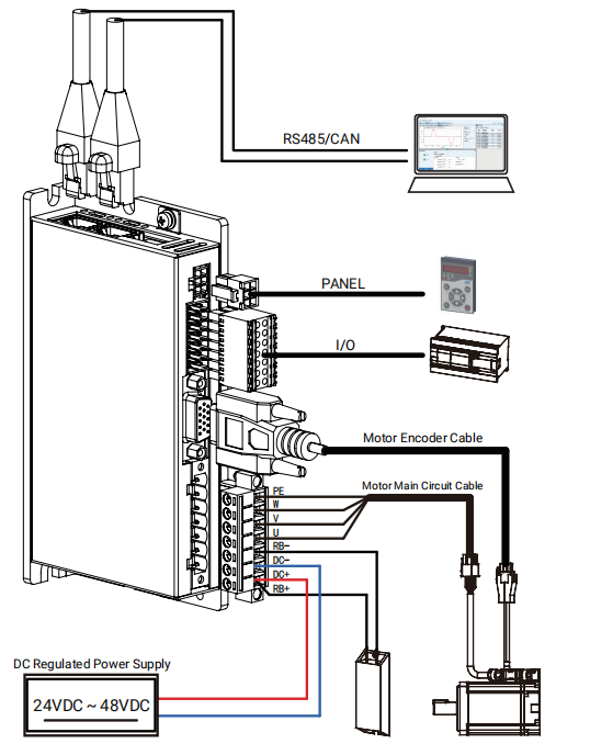
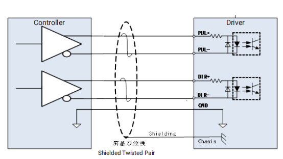
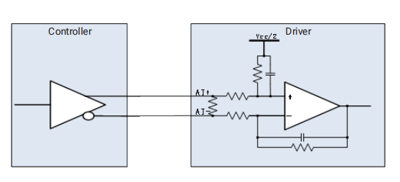
Note: If a 24V pulse signal is connected, a 2K resistor must be connected to the pulse signal line, and the power must be higher than 0.5W.
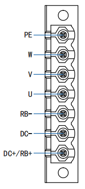
 Power & Motor Interface
     
Pin Name
Pin Function
PE
Motor Earthing Port
W
Servo Motor Power Supply Output Port
V
U
RB
External Braking Resistor Input Port
DC
Driver Power Input Port (negative) 
DC+/RB- 
DC+: Driver Power Input Port (positive)
RB+: External Braking Resistor Input Port

 Communication Interface
       
Pin No.
Pin Name
Pin Function
8
NC
Reserved
7
NC
Reserved
6
GND
Signal Ground
5
RX-
RS485-
4
RX+
RS485+
3
CAN_GND
CAN Signal Ground
2
CANL
CAN_L
1
CANH
CAN_H

 Encoder Interface
             
Pin No.
Pin Name
Pin Function
Pin No.
Pin Name
Pin Function
1 5V+
5V Power Supply Voltage Input Port
8 A
Encoder A-phase Signal Input Port
2 GND
Encoder Signal Earthing Port
9 W
Encoder W-phase Signal Input Port
3 / / 10 V
Encoder V-phase Signal Input Port
▲4 U
Encoder U-phase Signal Input Port
11 /Z
Encoder/Z-phase Signal Input Port
SD
Communication Encoder Data Bus Port (positive)
12 /B
Encoder/B-phase Signal Input Port
▲5 /U
Encoder/U-phase Signal Input Port
13 /A
Encoder/A-phase Signal Input Port
/SD
Communication Encoder Data Bus Port (negative) 
14 /W
Encoder/W-phase Signal Input Port
6 Z
Encoder Z-phase Signal Input Port
15 /V
Encoder/V-phase Signal Input Port
7 B
Encoder B-phase Signal Input Port
     
 Note: Select one from the two functions for Pin 4 and Pin 5.

S1 Series Servo Motor Driver Input/Output Wiring
General DI Input Wiring
ZDRV.S10 driver has DI1~DI4 four general DI inputs; through the DriverStudio, it can select different DI input functions; it supports NPN or PNP wire connecting mode; the recommended wiring diagram is as below:
PNP Connecting Mode
NPN Connecting Mode
 General DO Output Wiring
The ZDRV.S10 driver has DO1~DO2 two general DO outputs; it can select different DO input functions; it supports NPN or PNP wire connecting mode; the recommended wiring diagram is as below:
Relay Input for upper device
Optical coupler Input for upper device


Pulse Command Input Wiring Analog Command Input Wiring


Ningbo Zhongda Leader Intelligent Transmission Co., Ltd is a High-tech public enterprise specializing in research & development, manufacture, sales and service of motor driver, micro motor and high precision gearbox. August 29, 2017, Zhongda went public in the Shenzhen Stock Exchange SME board A-shares (stock code 002896), As a one of the powerful S1 Series Low Voltage Servo Driver manufacturers and S1 Series Low Voltage Servo Driver suppliers in China. our company Participated in the drafting of 7 National Industrial Standards, Own 90 national patents, Have Zhejiang provincial enterprise R & D Center, our S1 Series Low Voltage Servo Driver and other products are widely used in industrial robots, intelligent logistics, new energy, machine tools and other fields, as well as special machinery and equipment for food, packaging, textile, electronics, medical, etc. for their differentiated and cost-effective advantages.

No. of Employees: 1,500 employees

Mission: Zhongda realizes the infinite possibilities in automation applications.

Main Business: It is a High-tech public enterprise specializing in research & development, manufacture, sales and service of motor driver, micro motor and high precision gearbox.

Main Products: Micro DC & AC gear motor, small AC gear motor, planetary gearbox, high precision cycloidal gearbox and motor driver, etc.

Tips: Not all gearbox catalogue listed. Feel free to inquire and get latest catalogue. Need solution? We'd like to help.

Show Information

News & Media

How Efficient Are Planetary Gearboxes Compared to Traditional Gear Systems?

Industry News

How Efficient Are Planetary Gearboxes Compared to Traditional Gear Systems?

In the realm of mechanical engineering, the efficiency of gear systems is a critical factor influencing the performance and energy consumption of vari......

What Makes Planetary Gear Motors Tick? A Deep Dive into Precision Engineering

Industry News

What Makes Planetary Gear Motors Tick? A Deep Dive into Precision Engineering

Planetary gear motors have become indispensable components in various industries, driving efficiency and performance to new heights. But what lies ben......

How to evaluate the accuracy and stability of planetary gearboxes

Industry News

How to evaluate the accuracy and stability of planetary gearboxes

Assessing the precision and stability of a planetary gearbox is crucial to ensure its optimal performance and reliability in various applications. In ......

How do the materials of internal components affect the performance of a Planetary Gearbox?

Industry News

How do the materials of internal components affect the performance of a Planetary Gearbox?

Planetary gearboxes play a crucial role in various mechanical systems, offering versatility, efficiency, and power transmission capabilities. However,......

How does the temperature rise of an AC gear motor affect its performance and life?

Industry News

How does the temperature rise of an AC gear motor affect its performance and life?

In our daily life and industrial applications, AC gear motors have long become an indispensable source of power. However, during continuous operation,......

What processing technology is used for planetary gearboxes?

Industry News

What processing technology is used for planetary gearboxes?

As a well-known enterprise in the planetary gearbox industry, our company is always committed to providing customers with high-quality, high-performan......